

Description
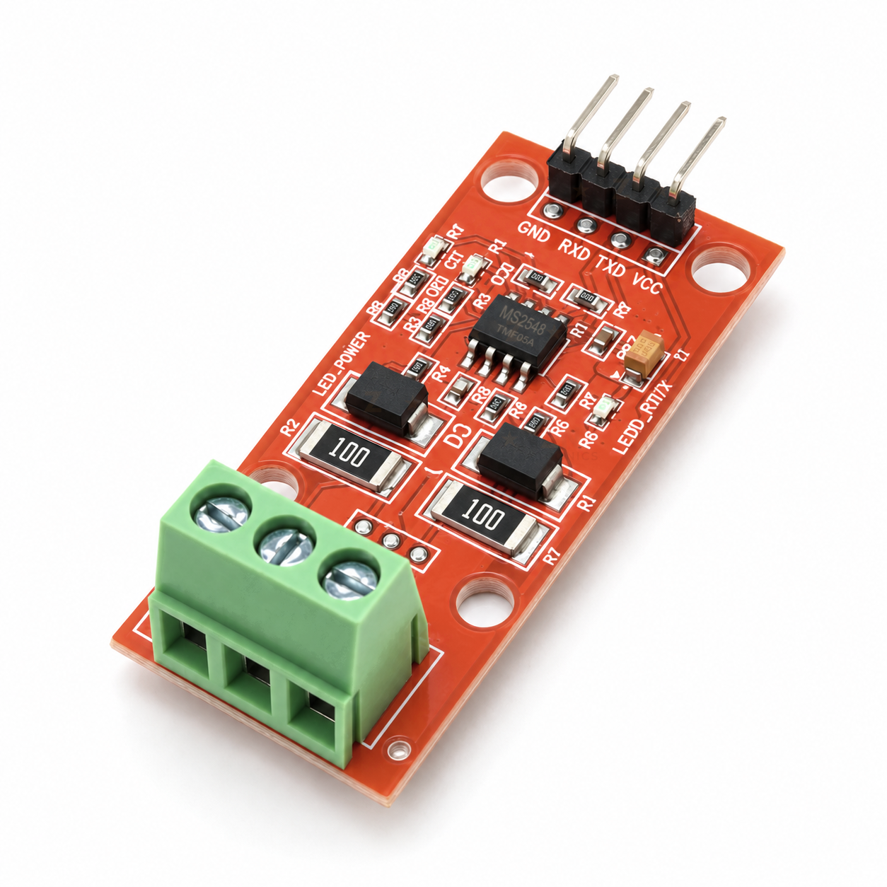
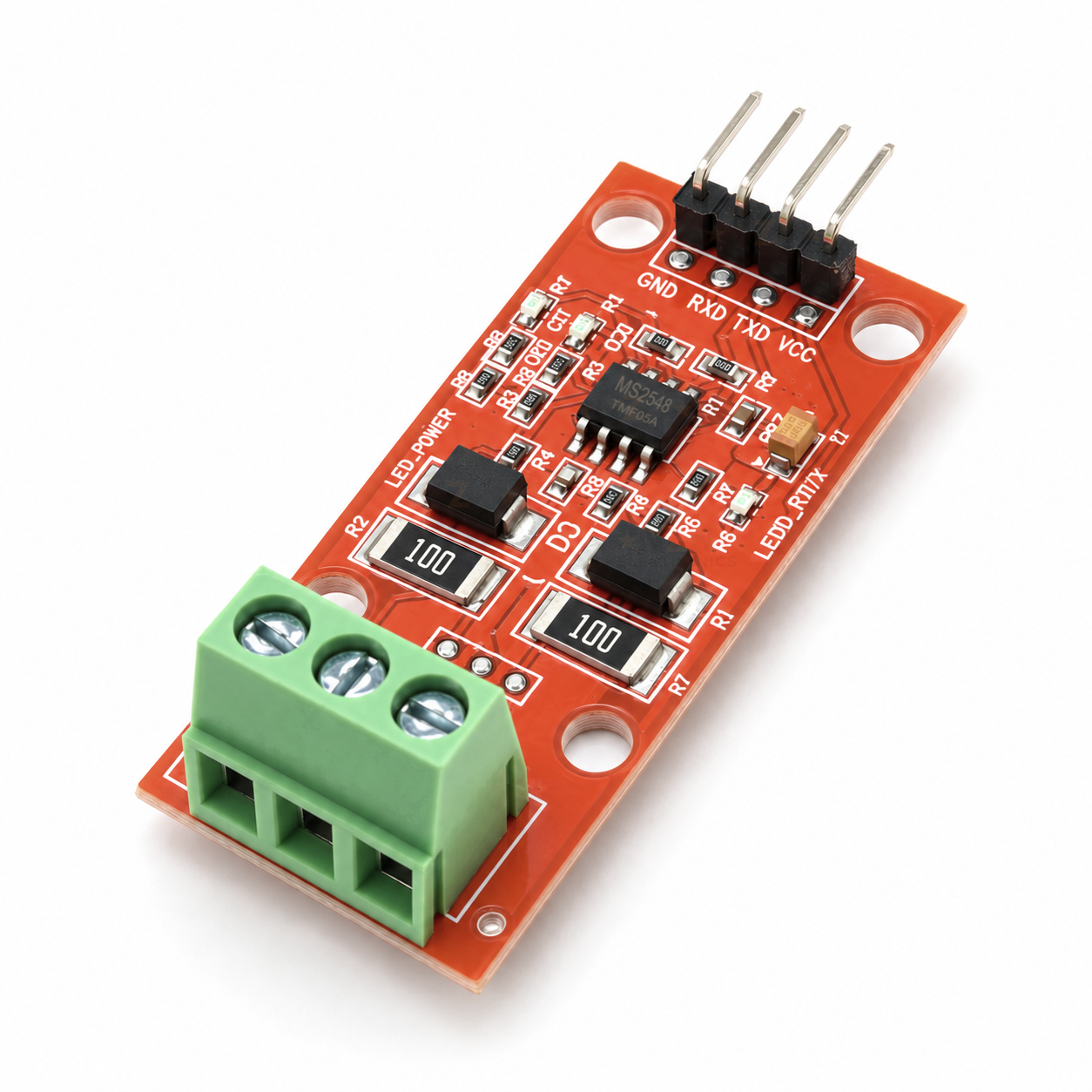
Connect a microcontroller UART to a two-wire RS485 bus with this MS2548 module. It runs from 5V, and the MS2548 transceiver switches between transmit and receive by itself, so no direction-control pin is needed. The header pins are named from the module’s side: RXD is the module’s input and takes your controller’s TX, and TXD is its output to your controller’s RX. A 5V board such as an Arduino Uno wires straight on. For a 3.3V board such as an ESP32, follow the wiring steps below.
Specifications
Datasheets
What’s in the box
Red HW-144 board with a fitted right-angle 4-pin header and a green 3-way screw terminal.
Great for
Wiring & getting started
-
Connect power with the circuit off
Connect a regulated 5V supply to VCC and join the controller and module grounds. Do not run it from 3.3V.
-
Check which pin is which
Power the module from 5V with nothing connected to TXD or RXD, and measure each pin to GND. The output (TXD) reads close to the supply voltage. The input (RXD) reads lower.
-
Connect the UART, crossed over
Connect controller TX to the module’s RXD and controller RX to the module’s TXD, as the drawing on the back of the board shows. TXD outputs about 5V, so on a 3.3V board such as an ESP32 or Pico, bring it down with a level shifter or a divider: 10k from TXD to the controller’s RX pin and 20k from that pin to GND. We have not yet confirmed that this board’s RXD input reliably reads 3.3V logic, so run that line through a level shifter too.
-
Connect the RS485 bus
Connect D+/A to the remote A or + terminal and D-/B to the remote B or – terminal. Keep the polarity the same along the whole bus.
-
Set termination and start slow
Bridge 120_S only when this module is at a physical end of the cable. Start at 9600 baud and raise the speed once replies are reliable.





Reviews
There are no reviews yet.