

Description
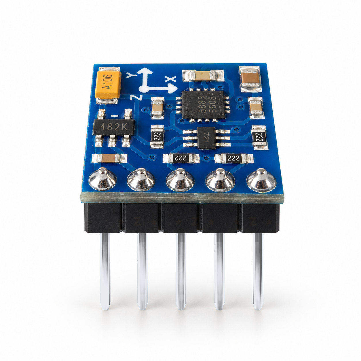
A GY-271 3-axis magnetometer board fitted with the QMC5883P sensor, for adding a digital compass heading or magnetic field readings to an Arduino, ESP32 or Raspberry Pi project. It runs from 3V to 5V and talks over I2C at address 0x2C, so it works with a QMC5883P library such as Adafruit QMC5883P, not the older QMC5883L or HMC5883L code. Choose Unsoldered with a loose header, or Soldered with the header already fitted.
Specifications
Datasheets
What’s in the box
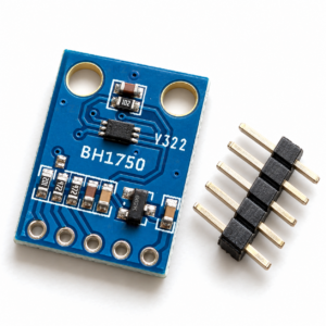
Unsoldered ships with a 5-pin 2.54 mm male header, loose and ready to solder. Soldered comes with the header soldered in, ready for a breadboard or jumper wires. Jumper wires and the microcontroller are not included.
Great for
Wiring & getting started
-
Fit the header
On the Unsoldered option, fit the short ends of the 5-pin header through the board and solder all five pads. The Soldered option is ready to go.
-
Wire four pins
VCC to 5V on an Uno or Nano, or 3V3 on an ESP32. GND to GND. SCL to A5 and SDA to A4 on an Uno or Nano, or GPIO22 and GPIO21 on an ESP32. Leave DRDY unconnected.
-
Install the library
In the Arduino IDE open Tools > Manage Libraries, search QMC5883P and install Adafruit QMC5883P with its dependencies.
-
Run the test sketch
Upload the sketch from the Quick Start and open the Serial Monitor at 115200 baud. It prints QMC5883P found, then X, Y and Z in gauss that change as you turn the board.
Note: For a compass heading, mount the board level and away from steel screws, magnets, motors and speakers, then calibrate it in place. In New Zealand add about 19 to 27 degrees east of declination to turn magnetic north into true north. The datasheet has a calibrated heading sketch.



Reviews
There are no reviews yet.