

Description
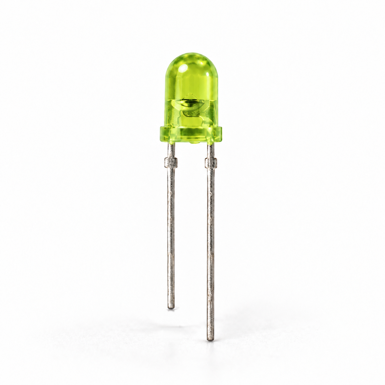
An LED is a small light that runs from a low DC voltage. It only lights when current flows one way through it, so it has to go in the right way round, and it needs a resistor in series to set its current. These are standard 3mm round-top through-hole LEDs with short legs, in six colours. Red, orange, yellow, green and blue have a lens tinted the same colour as the light, so you can tell them apart in the parts drawer and the colour still shows when they are off. White has a water-clear lens. The green is a yellow-green (568 to 570nm), the classic indicator green, rather than the deeper emerald green of a 525nm LED.
Use them for power and status lights, Arduino and ESP32 output tests, panel indicators in a 3mm hole, or teaching kits. The 2.54mm lead spacing plugs straight into a breadboard and fits standard 0.1 inch PCB pads. They are sold singly with a minimum of 10 per colour. Each LED needs its own resistor, which is not included; the 600-piece resistor kit has every value given below. If you would rather skip the resistor and the soldering, the 3mm pre-wired LEDs come with the resistor and 20cm leads already fitted for 5V or 12V. For a bigger 5mm lens, see the 5mm LEDs.
Specifications
Colour (peak wavelength)
Datasheets
Wiring & getting started
-
Find the positive lead
The longer lead is the anode (+). The shorter lead is the cathode (-), and the rim has a small flat on that side. If you trim the leads, the flat still tells you which is which.
-
Pick the resistor
Use one resistor for each LED. For red, orange, yellow or green: 150 ohm on 3.3V, 330 ohm on 5V or 1k on 12V. For blue or white: 220 ohm on 5V or 1k on 12V. These run the LED at about 8 to 10mA, plenty for an indicator. Blue and white have little voltage to spare on 3.3V, so they glow dimmer there (47 ohm gives about 2 to 6mA); run them from 5V if you want them bright.
-
Wire it up
Connect the supply positive, or a board output pin, to the resistor, the resistor to the long lead, and the short lead to GND. The resistor can sit on either side of the LED as long as it is in series. On a breadboard the LED and resistor push straight in; on a PCB, solder each lead for about 3 seconds and trim the ends.
-
Check it works
Switch on and the LED lights in its colour. If it stays dark, it is almost always in backwards: switch off, turn it round and try again.






Reviews
There are no reviews yet.