

Description
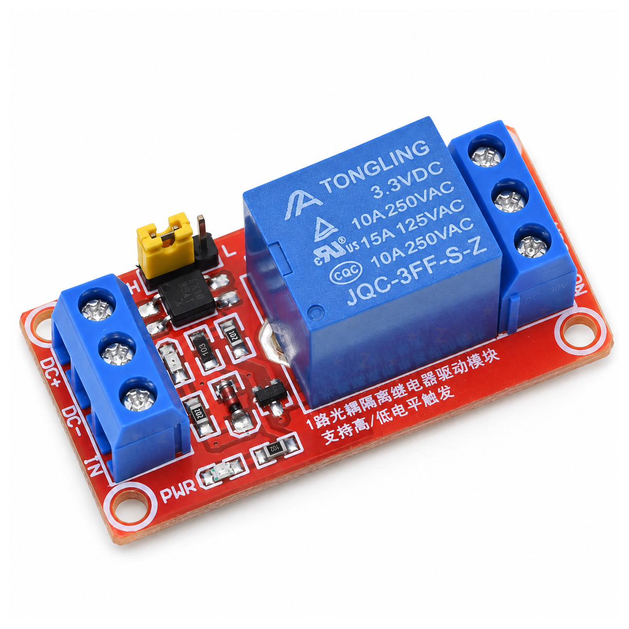
A single-channel relay board for 3.3V boards such as the ESP32, ESP8266 and Raspberry Pi Pico. It runs from 3.3V, switches a separate circuit with relay contacts rated up to 10A at 250VAC, and a jumper sets whether the input switches on with a high or low signal.
Using a 5V Arduino such as an Uno or Nano? Choose the 1-Channel 5V Relay Module instead.
Specifications
Datasheets
What’s in the box
Assembled board with screw terminals fitted.
Great for
Wiring & getting started
-
Set the trigger
With power off, move the jumper to H to switch the relay on with a high signal, or to L to switch it on with a low signal.
-
Power and signal
Connect 3.3V DC to DC+ and DC-. Join DC- to your board’s ground and connect its output pin to IN. Use a 3.3V rail with spare current for the relay coil, not a GPIO pin, and never connect 5V to DC+.
-
Test before adding the load
With nothing on the contacts, switch the input. The relay should click and the indicator light, and COM should connect to NO. When released, COM connects to NC.
-
Connect the load
Turn everything off. Run the load circuit through COM and NO to switch it on when triggered, or through COM and NC to switch it off when triggered. Stay within the load limits.
Note: Mains voltage can kill. Only wire mains loads if you are competent to do so, fully enclose the board so no terminal or solder joint can be touched, and follow NZ electrical safety rules. Motors and lamps draw a surge at switch-on, so leave margin below the limits.






Reviews
There are no reviews yet.